How to Improve the performances of DC Power supplies & DC motors
Basically a DC power supply consists of following -
- Step down transformer
- Rectifier ( Bridge Connection)
- Filter
- Regulator
- Regulated DC output
A standard, general purpose 24V-5Amp power supply is available at Lamington Road, Mumbai. But it consists of only first three elements of power supply i.e. Step down transformer, Rectifier (Bridge Connection) and Filter. If you check its rating using a Multimeter, you will find that its actual Voltage Rating & current Rating is something beyond the specified values. Its actually 35V (DC) 2Amp along with a comparable value of AC voltage !!


This AC is enough to hamper the performances of the DC devices (mostly DC Motors) which are powered using these messed up power supplies ( It cannot be called blunder as it is serving its purpose of giving DC output ). As the 'DC' Motors run on DC power, the AC voltage does not fit in the bargain, and hence needs to be restrained. And that can be done by adding the remaining two elements (4 & 5) of power supply.
There are many types of voltage regulators, like fixed & adjustable regulators, step up & step down regulators, positive & negative regulators etc. 78xx ICs are series of fixed regulators.Eg. 7805-5V regulator, 7812-12V regulator...L200 is a 5 terminal, voltage and current regulator. Most commonly used adjustable voltage regulators used are LM117, LM217, LM317, LM350 etc. You can either use IC LM7824 ( for 24 volts) or LM 317. LM317 is a 3 terminal adjustable positive voltage regulator capable of supplying greater than 1.5A current over an output voltage range of 1.2 to 37 volts ( For better flexibility use LM317)
For the datasheet, click here
Refer figure 1 in the datasheet for the circuit diagram and the expressions for Vi & Vo .
Impedance Matching:
Impedance matching is a concept dependent on maximum power transfer theorem, which states that to obtain maximum power at the output, input internal resistance must equals load resistance.
In case of a DC Motors, what we are concerned about is the current it can draw out of the source. For High torque motors, mainly current matters and not voltage ( That does not mean we should choose any value for voltage, but !5V is standard ). So following techniques can be implemented for better efficiency of DC motors -
- Use of Flyback Diode
- Connecting a Capacitor of specific value in parallel with the motor
- Type of wire used
- Use of Driver circuits
The DC motor can be visualized as a coil (inductor coil) connected in series with a resistance of small value, or simply as an electromagnet. When the Motor is disconnected from the supply, the magnetic field which was generated because of inductor coil, decreases as there is no current flowing through the coil. This change in magnetic field gives rise to what is known as back emf. Back emf or counter electromotive force is of several hundreds of volts. The circuitry which is controlling this motor invites an unnecessary risk of damaging the components present on the circuit. Hence to avoid this, we connect a diode across the motors. Flyback diode, freewheeling diode, suppressor diode, catch diode they all mean the same thing.
 |
| Image: wikipedia |
In Motor control and Robotics field, back emf is also referred to as the voltage generated in a spinning motor, which hampers the speed of rotation of motor. Even this can be avoided by connecting a diode across the motor, which results in increased effective rating of the DC motor.
But recall that a diode allows the current to flow in only one direction, hence allowing the motor to rotate in only a specific direction. Hence this technique is used specially for wireless cars and different programmable robots where we don't require backward motion (But don't use this technique for wired robots).
Connecting a Capacitor of specific value in parallel with the motor:
If you happened to open your remote controlled toy car, you must have seen a small ceramic capacitor connected across the DC motor. Ever wondered, why do we do that???
The DC motor consists of coils, brushes and permanent magnets. The current through the coils pushes them from one magnet to another and this turns the commutator, which switches the current around to continue this process in a cycle. This switching action causes the current drain of battery to vary up and down. The capacitor acts as a reservoir and buffer so that when motor draws little current, the capacitor recharges and when the motor needs high currents the capacitor discharges through the motor. You can use this technique for all kinds of Robots.
Use can also use both, capacitor and diodes for improved results for different competitions.
Type of Wires to be used:
Generally high torque motors require higher currents for their operation.
According to the equation of current,
i = dq/dt = n * e * vd * a
where,
n: No. of electrons
e: Charge on electron i.e. 1.6 x 10 ^ -19
vd: Drift velocity of electrons
a: Area of cross section
If the area of cross section increases, then the current carrying capacity of wire increases. So use copper wire of intermediate thickness for better results.
 |
| My Remote control box using thick wires |
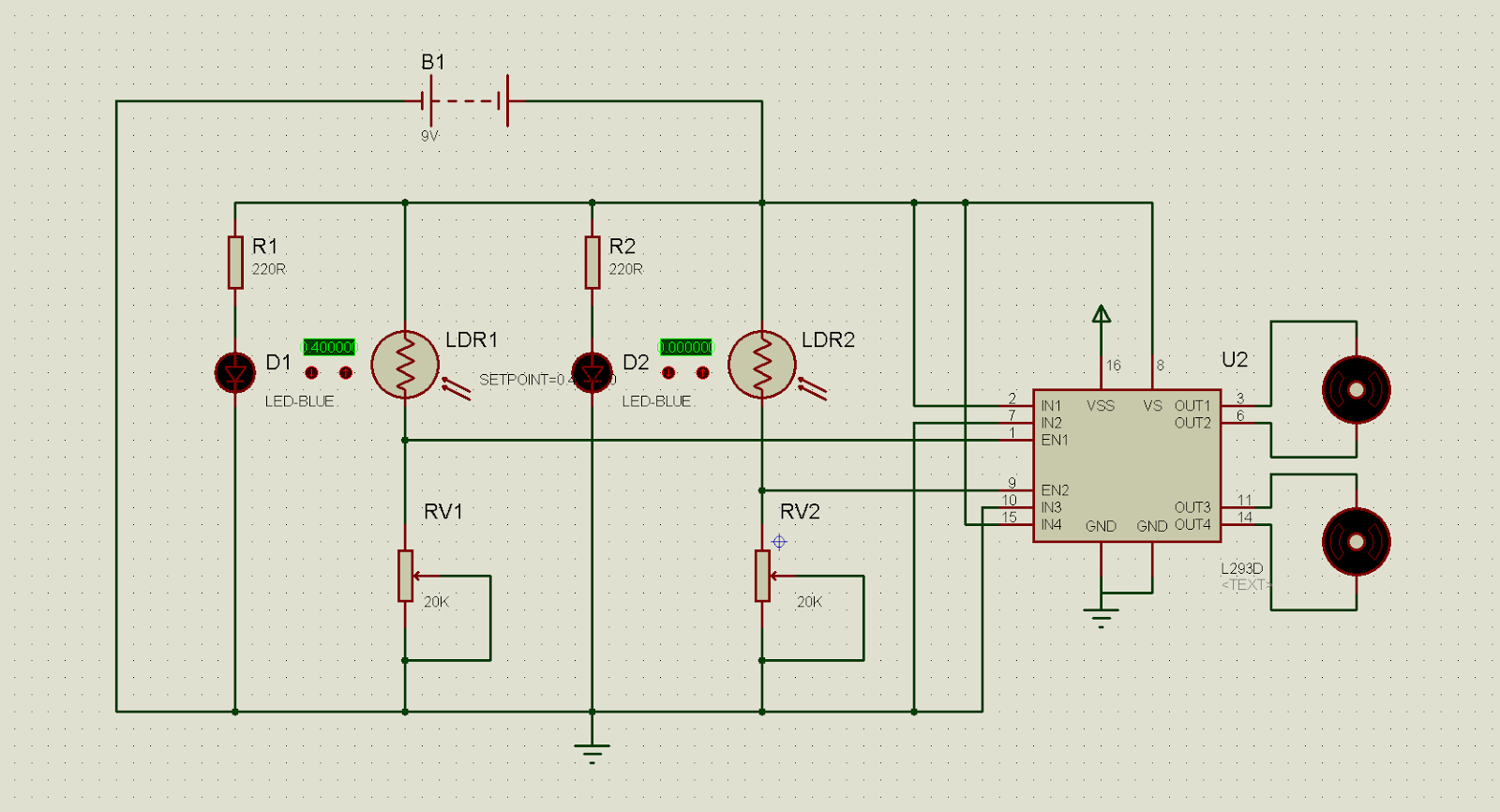
Driver circuits:
In order to operate a high torque DC motor ( specially used for Robowars & Fifabotix competitions in
MU ) sometimes the rating of even 25 volts and 2 Amp. is not sufficient. So, in order to tackle this issue there are Driver circuits, available in market. These drivers trade voltages for obtaining higher currents and vice versa. For example 25V and 2 Amp input to a driver can fetch us 15V and >10 Amp. of current!!
Their only disadvantage is that they are damn costly.

Comments
Post a Comment